Details on the Cell
© Alan Fletcher 2023-2025
Review of Li v4 8/23/26Review of Storms v4 8/23/26
Proposal v2 4/11/24
Cell Details v2 4/12/24
Li Papers
1. Safety
Deuterium and Hydrogen are involved!
The risk is slightly mitigated by using the smallest possible cylinders, and greatly reduced if a heavy-water system with electrolysis and recovery is used.
2. Summary
This is a proposal to replicate the 2003 Li (Tsinghua) LENR Cell.It is made from: a Deuterium gas supply, a container, a thin (0.1mm) disk of Palladium, a DC resistive heater, a calorimeter, and a Helium detector.
The expected outputs are heat, and helium.
Robust controls, using various isotope signatures, can eliminate all sources of contamination.
The initial version will use a 3D printed, high-temperature plastic. The operatring cost is mainly for heavy water, at about 1g ($1) per hour. 4/15/2023
3. Test Disks
A variety of disks will be tested -- all of a standard size.
H + Al as a dummy for calibration and single-side leak-tests.
H + Ni for diffusion tests and He-Detection
D + Untreated 0.1mm Pd (as in Li)
D + Treated Pd (eg Storms, film prepared externally)
D + Pd with Nano-slots (per Storms)
D + PdAg with Nano-slots (to prevent natural cracks and flaking).
4. Block Diagram
A block diagram of the cell is
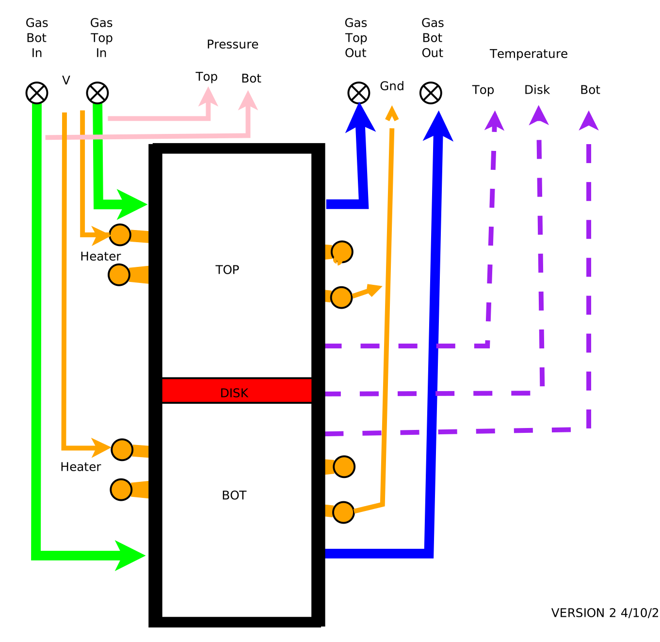
The cell is a cylinder (Black), mounted vertically, so it can fit in a Calvet calorimeter.
The cylinder is in two halves, with the disk holder between them.
A thin disk of test material (Red) is mounted, in a holder, in the center. Li calls the two chambers "Deuterium Room" and "Vacuum Room". Here they are just called "Top" and "Bottom".
Each chamber has an inlet gas tube (Green), with pressure sensors (Pink), and an outlet gas tube (Blue).
Each gas tube has a stop-cock (x), and can be connected externally to the gas supply, vacuum, or instruments as required.
A heating coil (Orange) is wrapped round each half of the cylinder.
Temperature recording devices are mounted above the disk, at the Disk, and below the disk.
Additional sensors may be mounted near the ends.
5. Calorimeter Test Cell
Note: this is an older configuration. The cell heater is actually in two sections.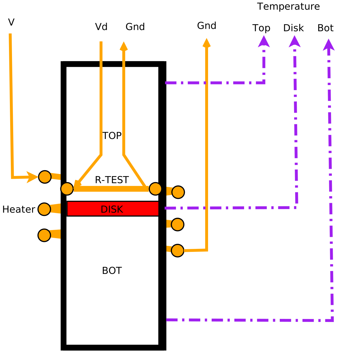
This has a heater located close to the test disk, with wires fed through the end-cap.
It would otherwise be identical to the regular cell (without in-cell detectors). It could be filled with a non-flammable gas with thermal characteristics similar to D2, or with H2.
As an example, the external heater could be set to 15W and the test heater power increased in steps to determine the accuracy and sensitivity of the calorimeter.
These can then be compared to the reference calorimeter.
6. Internal Instrumentation
A "detector" disk (cyan) could be added in four places -- at the Roof, above the disk, below the disk and on the floor.
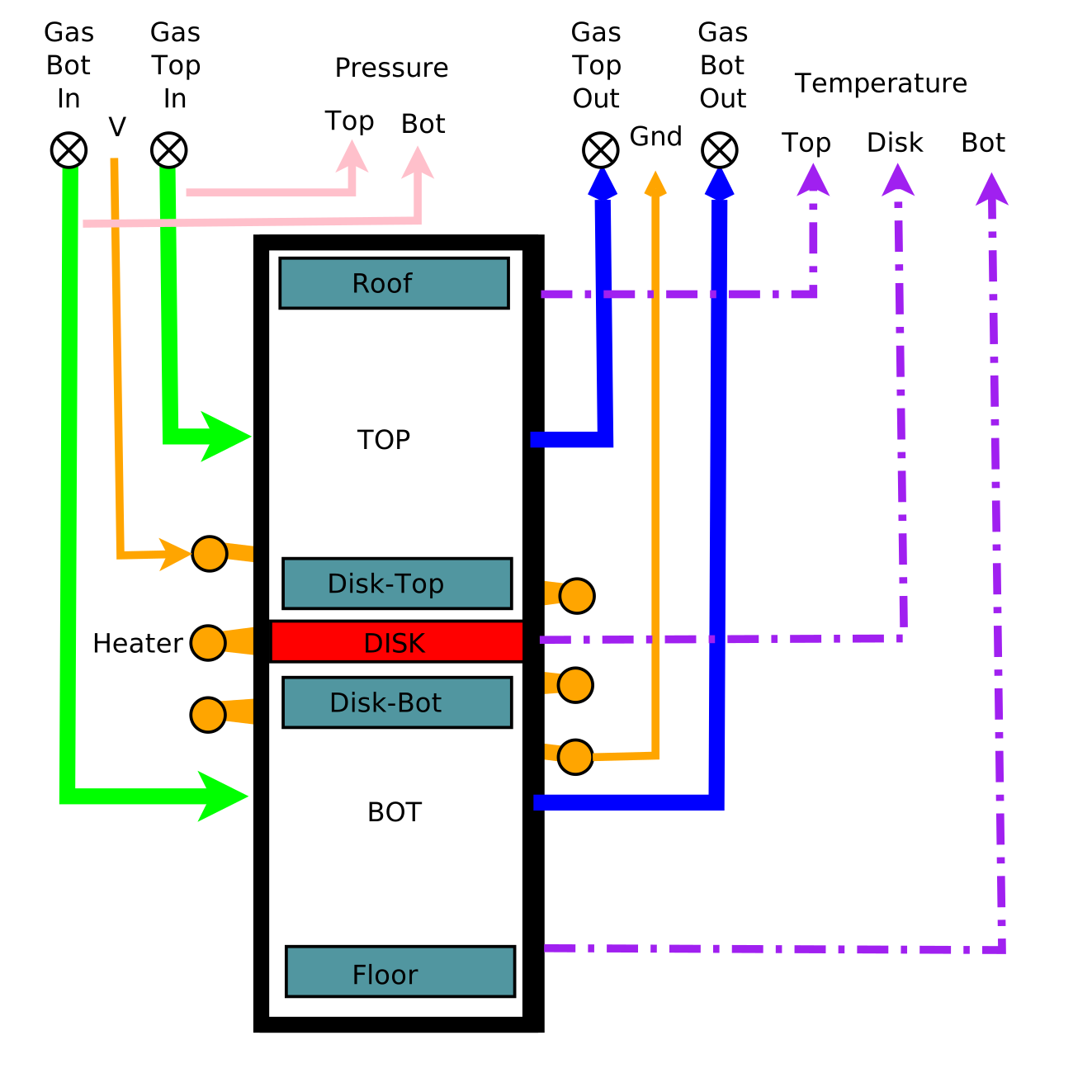
For the Disk-top detector we might use some combination of:
All of these will work in the range 20-200C.
- X-Ray film
- CR39 radiation detector
- Temperature-sensitive paint (which melts at a set temperature, causing a color change)
A future possibility would be to add an "active" detector disk, for instance an array of thin-film thermocouples.
This would either need multiple cables, but could be done with an electronics module. For example, there are Gate Arrays rated to work up to 200C and survive up to 300C.
7. External Instrumentation and Measurements
Recording of the following are straight-forward:
- Input power to the heater resistor
- Temperatures
- Pressure (0 to 10 bar) [ vaccum?]
Note : see the separate "gas flow" document. This summary will be rewritten.
One possibility for the gas flow is:
- D2 generated by Electrolysis
- In-line Gas flow measurement (D2) But flow may be too small, and not accurate
- Bleed to sampling / mass spectrometer / recovery
- Input stop-cock
- Input pressure gauge
- Output pressure guage
- Output stop cock
- Bleed to sampling / mass spectrometer / recovery
- In-line Gas flow (Note: but needs to be adjusted for D2/He mix)
- Helium / Deuterium separation and measurement
Many of the instruments chosen depend on the expected results. For a given cell I can calculate the rate of diffusion through Pd from the diameter, length, pressures and temperatures. From the expected excess energy and the MeV per DD->He4 I can calculate the expected Helium concentrations.
In-line mass flow instruments may not work at very low flows. It may be necessary to add more D2 as a carrier gas.
Li 2003 used 1 bar across the test disk, maybe because it will deform under pressure (There is a trade-off in diffusion rates between pressure and length). Liu 2014 used a 0.1mm plate at 40 bar.
Since the operating range is 20C to 200C all the proposed in-cell instrumentation will work.
(In the case of a thermal run-away they may give useful information before they die)
8. Contamination Avoidance and Detection
The beauty of the Li cell is that, in the absence of any in-cell instrumentation, it contains only
- Steel (or composite)
- Palladium
- Deuterium
- A few gas-seals (if a problem, a steel cell could be welded shut.)
- Aluminum for blank runs
- Silver if we use PdAg
If we discover anything else (eg by mass spectroscopy) then it is either
- Contamination
- The result of a LENR transformation
Copper is fairly easy to avoid. If we need in-cell connectors we can use silver or aluminum.
The background atmospheric concentration of Helium is about 5 ppm. We need to make sure that doesn't get into our system.
Unfortunately He4 is the common isotope, so we have to rely mostly on contamination avoidance.
Except for the Li replication with a vacuum, the entire gas-system will be positive-pressure.
There will be a pressure-gradient through the system, so there is no possibility of reverse flow.
Unfortunately in LENR we have to deal with hyper-skeptics, who tend to believe that the laws of nature are suspended or reversed. Or that events occur that are even less likely than the one being studied.
One possible scheme would be to "seed" the system with specific isotope combinations.
eg N14 vs N15 : Ar 40 vs Ar36,38 O16 vs O17,18
eg
I0 is the natural composition.
I1 is N15
I2 is 90% N14, 5%Ar36
...
Initial assembly is in N15 -- If we see that it means we didn't flush the system correctly.
If we see natural N14 it means there was an atmospheric leak.
9. Other concerns
It is presumed that if Helium is produced it will be well-mixed with the D2. If it is stratified it might need to be stirred, or a carrier-gas supply of D2 might keep it stirred. This kind of detail can be ignored until we know the expected D2 diffusion rate and the He production rate,
10. Engineered Nano-Gaps (Future)
Once we have settled on a cell geometry we can investigate how to manufacture test disks.
We want gaps in the range of 2 to 20 nm. I suggest the length should be at least 5 * width.
(Round holes and though-slots should not be used.)
What depth do we need?
Initially I think we should make a range of slot-sizes on a test disk.
Hopefully the Li Cell will pick up the signal even if only one zone "fires".
The in-cell instrumentation should be able to identify active zones.
Since we do NOT want "natural" gaps (cracks or flakes) we should also try PdAg.
11. Experiments
This section is an active draft ...
a) Pressure Test
Initial tests may be done with Hydrogen and either Aluminum or Nickel (diffusion).
Just set up the cell with hydrogen gas input, a heater.
Alternate with gas and vaccum to flush the system. Vent the gas safely, or catch in bell jar.
Turn off the gas and turn on the heater. Record the stable temperature.
Turn on the gas at its highest pressure and record the temperature. If it increases we have LENR.
b)Diffusion Test
This can be done with H and Ni including recovery.
7.1 System tests and calibration.
Initial system checks can be done with an Aluminum disk.
- A pressure test could be done with a non-flammable gas such as Nitrogen.
- A "calibration." mix of D2 and He could be used to test the external instruments.
A 2-D sweep of Pressure and Heater Temperature should show no abnormalities (See Li 2003)
7.2 Active tests and calibration.
The test disk and passive instrumentation are loaded into the cell.
A pressure test could be done with a non-flammable gas such as Nitrogen.
The heater can be tested at this stage.
The entire system should then be flushed with D2 (maybe with vacuum cycles), and a D2 pressure test done.
Loading Run :
The first run is a loading run, and should probably be done at high input pressure and temperature.
Other runs: A 2-D sweep of Input Pressure and Heater Temperature
(Li only did a temperature sweep.)
The cell is removed, and the system is flushed with Nitrogen.
The cell
opened (in a clean room) and the disk and passive detectors analyzed.
12. Other Test Cell Variations
Following the planned equipment shown at the end of Li 2003, an end-cap could be made of transparent material, and the surface of the disk on that side viewed with (eg) an infrared thermometer, looking for hot spots (particularly for zones of a specific nano-gap size).
A "bomb" (single-shot) cell could be made with an internal D2 tank and an external stop-cock connecting it to the chamber with the test disk. The pressure difference across the cell would decrease during the run depending on the gas flow. This could be shipped to (eg a calorimetry group) that is not equipped to handle hydrogen and then returned for analysis of the residual gases and instrumentation.
It might be possibly to include in-cell electronics, connected via a USB interface. For example, Gate Arrays are available that work to 200C and survive at 300C.
However, I have not yet found an electrical connector through the wall of the cylinder that is hydrogen-tight and which is rated to 200C.
(A) Table Li vs AF
| Feature | Li | Modified |
|---|---|---|
| Vessel | Cylinder divided into two rooms | Cylinder divided into two rooms |
| Construction | Steel | Steel or Composite |
| Sample | Disk Film in mount | Disk or Square film in mount |
| Gas Supply | Cylinder | Electrolysis of H2O or D2O |
| Room A gas input | Constant pressure D2 1 bar | Variable pressure D2 0 to 3.5 bar |
| Room A gas outlet | None | Sealed, or D2 for analysis and recovery |
| Room B gas input | None | Sealed, or Variable pressure D2 0 to 3.5 bar |
| Room B gas output | Deep vacuum | Soft Vacuum, or analysis and recovery |
| Heater | External Coil in middle | External coil in middle, or offset on each side of the central disk |
| Thermometer | Central | Central and near the heaters |
| Pressure | None (assumed 1 and 0 bars) | One per room |
| Internal Detectors | None | None, Four (CR39, XRay,Thermal) |
| Visible eg IR | None | Not in first version |
| Gas Sampling | None | Sample points or In-line analysis |
| Calorimetry test | None | Resistor(s) at Sample |
| Active Side | Room A | Room A and/or Room B |
| D2 recovery | No | Attempted |
| He recovery | No | He-to-D ratio improved |
| D2 Consumption | Not clear. For cylinder could be by weight, or from PVT | From D20 weight and/or levels |